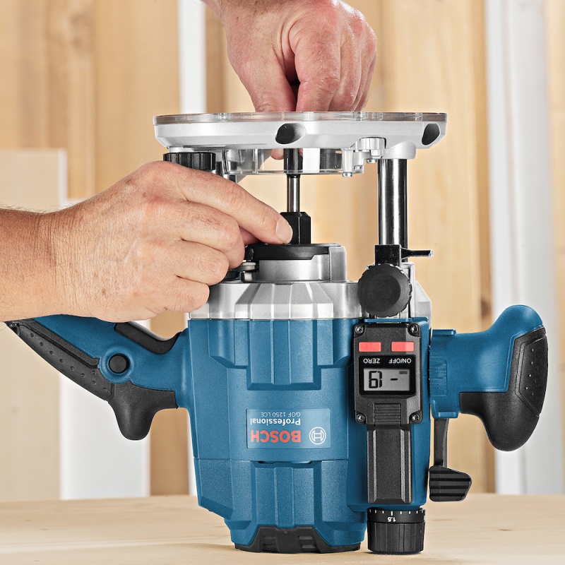
Router depth control determines how far a router bit extends into the workpiece. For a plunge router, set the bit at the workpiece surface, zero the depth scale, adjust the depth rod or stop to the required measurement, lock the setting, and verify the cut on scrap before routing the finished piece.
For woodworkers in the United States, router depth control is one of the basic setup skills that determines whether a groove, dado, mortise, rabbet, hinge recess, or decorative profile reaches the intended dimension. Most American woodworking references and router scales commonly use inches, so understanding fractions such as 1/8 inch, 1/4 inch, and 3/8 inch is especially useful when setting up a handheld router.
The exact adjustment procedure depends on the router base. A plunge router normally uses a depth rod, depth stop, turret, scale, and plunge lock to limit how far the motor and bit travel. A fixed-base router generally changes bit height by moving the motor within the base. In both designs, the most reliable approach is to establish a clear zero point, make the depth adjustment with the tool disconnected from power, lock the setting securely, and confirm the result with a test cut.
Source: s3.amazonaws.com
What Is Router Depth Control?
Router depth control is the system used to determine how far a router cutter enters the workpiece. The setting establishes the maximum cutting depth when using a plunge router and the bit height when using a fixed-base router or router table. A correct setting helps produce consistent dimensions across repeated cuts.
The reference point is usually the surface of the workpiece or the router table. If you need a 1/4-inch-deep dado, for example, the cutting edge should enter the material 1/4 inch from that reference surface. The router’s depth scale helps establish this distance, but the scale should not automatically be treated as more accurate than a physical test or measuring method.
Depth control becomes particularly important when the cut affects joinery. A groove that is too shallow may leave a poor-fitting joint, while a mortise or recess that is too deep can weaken the part or create an unwanted opening on the opposite side.
Source: wonkeedonkeetools.co.uk
Depth rod
A vertical rod on many plunge routers limits downward travel by contacting a selected stop.
Depth stop turret
A rotating turret provides multiple stop positions for stepped cuts and repeatable depth changes.
Plunge lock
The plunge lock holds the router at a selected position during a cut or while establishing the reference setting.
Depth scale
The scale indicates the approximate amount of plunge or height adjustment, often in inches and sometimes metric units.
Fine adjustment
Some routers provide a threaded micro-adjustment that allows smaller depth changes after the coarse setting has been established.
Router Depth Control vs. Bit Cutting Length
Router depth control and router bit cutting length are different measurements. Depth control determines how far the router is set to cut into the material, while the bit’s cutting length describes how much of the cutter is capable of cutting. A bit with a long cutting edge does not mean the router should be plunged to that full length.
The shank must remain properly secured in the collet according to the router and bit manufacturer’s instructions. Never compensate for an incorrect bit setup simply by changing the depth adjustment.
Depth setting
Controls the intended penetration of the cutter into the workpiece.
Cutting length
Describes the usable cutting portion of the router bit.
Bit engagement
Should remain within the manufacturer’s intended operating limits for the bit and application.
How to Set Router Depth on a Plunge Router
The basic plunge-router method is to establish zero with the bit touching the reference surface, then move the depth stop by the required amount. The controls differ among brands and models, so the owner’s manual should take precedence when its procedure differs from this general method.
Before making the adjustment, disconnect the router from its power source. This prevents an accidental start while your hands are near the cutter or depth mechanism. Install the correct bit according to the router and bit instructions, but keep the tool disconnected while setting the depth.
Place the router on the workpiece or another flat reference surface appropriate for the cut. Unlock the plunge mechanism, lower the router carefully until the bit just touches the reference surface, and lock the plunge mechanism. This establishes the zero position.
Next, loosen the depth rod or its locking screw so the rod can move. Position the selected turret stop below the rod if the router uses a turret system. Set the scale to zero if the design requires a zeroing step, then move the depth rod to the desired cutting depth and tighten the locking mechanism securely.
Unlock the plunge mechanism and allow the router to return to its normal raised position. Before cutting the project, check that the router can reach the intended depth without the bit or base contacting anything that should remain untouched.
Source: boschtools.com
1. Disconnect power
Unplug a corded router or remove the battery from a cordless model before making depth or bit adjustments.
2. Establish zero
Lower the bit until its cutting point just contacts the selected reference surface.
3. Lock the reference position
Secure the plunge mechanism or adjustment system according to the router design.
4. Set the depth stop
Move the depth rod or adjustment mechanism to the required measurement.
5. Secure the adjustment
Tighten the depth rod, knob, lever, or locking screw firmly without forcing a component beyond its design.
6. Verify the result
Make a test cut in scrap material that matches the actual workpiece whenever the dimension is important.
Using the Turret for Multiple Depths
A turret stop is useful when a cut needs to become progressively deeper. Instead of setting one final depth and removing all the material at once, the router can be adjusted through several predetermined stop positions. This is particularly useful for deeper mortises and other cuts where controlled passes are preferable.
After each pass, the router can be raised, the turret moved to the next appropriate stop, and the next pass made. The exact number and spacing of turret positions varies by router model, so use the positions provided by the manufacturer rather than assuming every turret has the same increments.
Shallow first pass
Begin with a controlled amount of material removal rather than immediately attempting the full depth.
Intermediate stops
Use available turret positions to establish repeatable additional depths.
Final pass
Use the final stop to reach the specified finished depth and then verify the result.
How to Adjust Depth on a Fixed-Base Router
A fixed-base router normally changes cutting depth by moving the motor up or down within the base. The router is not designed to plunge freely during the cut in the same way as a plunge base. Instead, the motor position is established before routing and then locked.
With the router disconnected from power, install the appropriate bit and place the base on a stable reference surface. Loosen the motor-height locking mechanism according to the model’s instructions, then adjust the motor until the bit reaches the reference position. Many routers allow the depth scale or ring to be zeroed at this point.
After zeroing, turn or slide the height-adjustment mechanism to the desired depth. Secure the locking mechanism and check that the motor does not move when moderate hand pressure is applied. If the router is mounted in a table, the procedure changes because bit height is established relative to the table surface rather than a handheld base.
Source: m.media-amazon.com
Coarse adjustment
Moves the motor or bit quickly toward the required height.
Micro adjustment
Provides smaller changes when the router has a fine-adjustment mechanism.
Locking mechanism
Secures the motor at the selected height so the bit does not drift during routing.
Test cut
Confirms the actual depth in the material instead of relying only on the scale.
Router Table Depth Control
When a router is mounted under a router table, the cutting height is referenced from the tabletop. The bit is raised or lowered until the exposed cutting edge reaches the required height. A combination square, setup block, height gauge, or another suitable measuring device can make the setting easier to verify.
The important distinction is that router-table bit height is measured upward from the table, while a handheld plunge-router depth is commonly described as the distance the bit moves below the workpiece surface. Always identify the reference surface before interpreting a measurement.
Reference surface
Use the router table surface as the height reference for a table-mounted router.
Measure the exposed cutter
Check the actual portion of the cutting edge above the table when the profile requires a specific height.
Make a scrap test
Confirm the profile and height using scrap material before routing finished stock.
Choosing the Correct Router Depth for Common Cuts
The correct router depth depends on the joint, hardware, material thickness, bit geometry, and the amount of material that needs to be removed. There is no single depth that is appropriate for every application.
For a shallow decorative groove or hinge recess, the target dimension may be only a fraction of an inch. For a deeper mortise, the final depth may require several passes. When the cut has to fit another component, measure the mating component rather than relying on a generic depth recommendation.
As a practical example, suppose a woodworking project calls for a 1/4-inch-deep groove. The target is 1/4 inch from the reference surface to the bottom of the groove. If a first pass removes 1/8 inch and a second pass removes another 1/8 inch, the final target is reached through two controlled operations. This is a hypothetical setup example; the appropriate number of passes depends on the material, bit, router, and manufacturer’s guidance.
Source: images.ctfassets.net
Decorative grooves
Use the design dimension as the target and confirm the appearance with a scrap cut before routing the final piece.
Dadoes
Set depth based on the joint design and the thickness of the material that will fit into the dado.
Mortises
Determine the required depth from the mating tenon or hardware and consider multiple passes for deeper cuts.
Hinge recesses
Measure the hinge leaf thickness and account for the desired fit rather than automatically using a standard depth.
Rabbets
Set the depth according to the shoulder dimension required by the joint or assembly.
A Simple Depth Calculation
For a basic plunge cut, the final depth can be treated as the distance from the reference surface to the bottom of the finished cut. If the target is 3/8 inch and the first pass is 1/8 inch, the remaining material to remove is 1/4 inch. A second 1/8-inch pass followed by a final 1/8-inch pass would reach the target.
This calculation is useful for planning, but it does not determine how much material should safely be removed per pass. That decision depends on the router, cutter diameter, material, grain direction, cutting speed, and manufacturer instructions.
Target depth
The finished dimension required by the project.
Current depth
The amount already removed from the reference surface.
Remaining depth
Target depth minus the depth already removed.
How to Improve Router Depth Accuracy
A router’s printed scale is a starting point, not a substitute for verification when the cut has a tight dimensional requirement. Scales can be difficult to read, and small differences in bit position, reference surface, or adjustment technique can affect the finished result.
For accurate work, establish the zero point carefully and use a physical gauge, setup block, drill bit spacer, or measuring device when appropriate. A spacer with the same thickness as the desired plunge depth can provide a direct reference without requiring the operator to interpret a small scale.
Test cuts are especially valuable when working with expensive hardwood, finished panels, joinery, or parts that must match another component. Use scrap material of the same thickness and, when possible, the same species and orientation as the finished workpiece.
Source: acmetools.com
Use a physical reference
A known-thickness spacer or setup block can provide a direct mechanical reference for the desired depth.
Zero carefully
Make sure the bit actually contacts the intended reference surface without forcing the cutter into it.
Lock before cutting
Secure the depth rod, plunge lock, or motor-height mechanism so the setting cannot shift.
Test on matching scrap
Use material with similar thickness and characteristics to the project stock whenever possible.
Measure the finished cut
Use a suitable rule, caliper, depth gauge, or mating component to verify the actual result.
Why the Router Scale May Not Match the Finished Cut
Several factors can create a difference between a scale reading and the actual cut. The zero point may have been established against the wrong surface, the bit may not have been seated as intended, the depth rod may have moved while being locked, or the workpiece may not have been held flat.
A router scale also describes the movement of the router mechanism, not necessarily the final dimension of a particular joint. Bit geometry, guide bushings, templates, table inserts, and the chosen reference surface can all affect what the measurement means.
Wrong reference
The router may have been zeroed against a surface different from the one used for the actual cut.
Loose adjustment
An insufficiently secured depth rod or motor lock can allow the setting to change.
Workpiece movement
A piece that shifts or rocks during routing can produce an inconsistent depth.
Measurement error
Small scale markings can be difficult to read accurately, particularly when the pointer or cursor obscures part of the scale.
Common Router Depth Control Mistakes and Safety Checks
Most depth-setting problems come from setup errors rather than from the basic concept of the adjustment system. The safest troubleshooting order is to disconnect power, inspect the bit and collet, verify the reference surface, re-establish zero, reset the depth control, and make a test cut.
Never make a depth adjustment with the router running. Your hands may need to approach the cutter, depth turret, or other moving components. Manufacturer instructions also commonly require the tool to be disconnected before certain setup and maintenance operations.
Do not assume that a deeper cut is automatically better. Removing excessive material in one pass can increase cutting load and make control more difficult. For deeper grooves, mortises, and similar operations, use an appropriate sequence of passes based on the router, bit, material, and manufacturer’s instructions.
Source: cahema.pe
Adjusting while powered
Disconnect the router before changing the bit, depth stop, turret, or other setup components that place your hands near the cutter.
Skipping the zero position
Without a reliable reference point, the scale reading may not represent the depth you think it does.
Failing to lock the setting
A loose depth mechanism can move during routing and produce an incorrect or uneven cut.
Taking an unnecessarily deep pass
Large material removal can increase cutting load and reduce control; use multiple passes when appropriate.
Ignoring workpiece stability
Secure the workpiece so it cannot shift while the router is being guided across it.
Relying only on the printed scale
For dimension-critical work, verify the actual cut using scrap material and an appropriate measuring method.
What to Check When the Router Will Not Reach the Correct Depth
First, disconnect the router from power. Confirm that the bit is installed correctly and that the router base or plunge mechanism can travel through its normal range. Then check whether the depth rod is contacting the intended turret stop and whether the locking mechanism is actually securing the setting.
If the bit reaches the desired depth mechanically but the finished cut is wrong, check the reference surface and workpiece position. A template, guide bushing, spacer, or base accessory can change the relationship between the router and the surface being cut. If the adjustment system appears damaged, loose, or unable to lock, stop using the tool until it has been inspected or serviced according to the manufacturer’s instructions.
Bit installation
Confirm that the correct bit and collet arrangement are being used and that the bit is properly secured.
Plunge travel
Check that the plunge mechanism is not being restricted by a lock, stop, accessory, or obstruction.
Depth rod contact
Verify that the rod meets the intended turret or stop rather than another component.
Workpiece reference
Confirm that zero was established against the same surface used to define the finished depth.
Frequently Asked Questions
Q
How deep should a router cut in one pass?
There is no universal maximum depth for every router, bit, and material. The appropriate pass depth depends on cutter diameter, material, router power, bit design, grain direction, and manufacturer guidance. For deeper cuts, several controlled passes are commonly used rather than removing the full depth at once.
Q
How do you set a plunge router to a specific depth?
Disconnect the router from power, establish zero with the bit touching the reference surface, lock the plunge position, move the depth rod or stop to the required measurement, secure the adjustment, and verify the result with a test cut. The exact control sequence varies by router model.
Q
Can you use a ruler to set router depth?
Yes. A ruler or small square can be useful for establishing or checking a router depth, provided it can be positioned safely and read accurately. For tight tolerances, a suitable setup block, spacer, depth gauge, or test cut can provide a more reliable verification.
Q
Why is my router depth changing during a cut?
A changing depth can result from an improperly locked plunge mechanism, loose depth rod, motor-height lock that is not fully secured, interference with the turret, or movement of the workpiece. Disconnect the router and inspect the complete adjustment system before making another cut.
Q
Is plunge depth the same as router bit cutting depth?
Not necessarily. Plunge depth describes the movement or position of the router mechanism relative to its reference point, while cutting depth describes how far the cutter actually enters the workpiece. Accessories, reference surfaces, bit geometry, and setup can affect the relationship between the two measurements.
✦ Wrapping Up
Conclusion
Router depth control is fundamentally about establishing a reliable reference point and controlling the position of the cutting bit relative to that surface. Plunge routers typically use a depth rod, turret, scale, and plunge lock, while fixed-base routers generally adjust the motor height inside the base. Router tables use the tabletop as the primary height reference.
For accurate woodworking, do not depend on the printed scale alone when the finished dimension matters. Establish zero carefully, lock every adjustment, secure the workpiece, use appropriate cutting passes, and confirm the result on scrap before committing to finished material. Always follow the specific safety and operating instructions supplied with your router and router bits.
💡 Key Takeaway
Before your next routing operation, disconnect the router, install the correct bit, establish a true zero point, set the required depth, lock the adjustment, and make a test cut in matching scrap. Measure the test result before routing the finished workpiece.